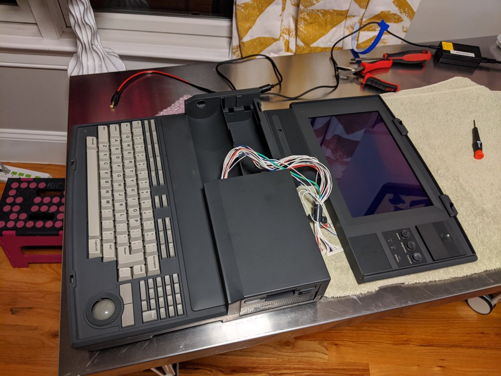
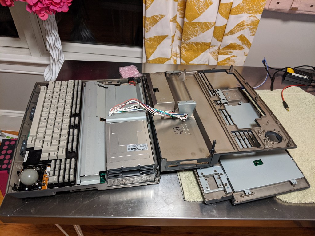
The time arrived to disassemble the body of the Stacy. In general, it wasn’t as difficult as expected, but there is one part that requires to have patience.
The first step is disconnect all the cables coming from the body to the screen section (except, in my case, for the LCD power cables that I soldered to the pad, although eventually I did it); then remove the 2 screws holding the plastic “tube” that holds them at the entrance of the body. Move the tube as close to the connectors as possible:
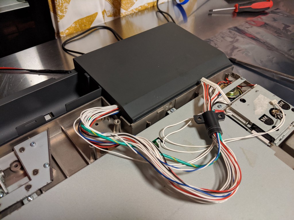
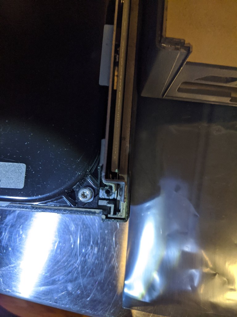
One by one, pass each connector through the plastic tube, starting with the small connectors (to make space) and finally the big ones (of course, you need to start with one side of the connector). Now, focus your attention to the hinge to the left, with the hefty spring:
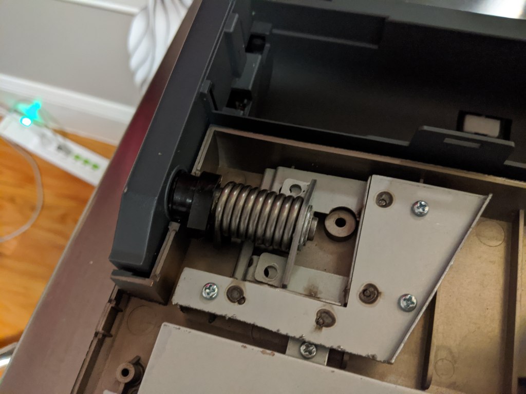
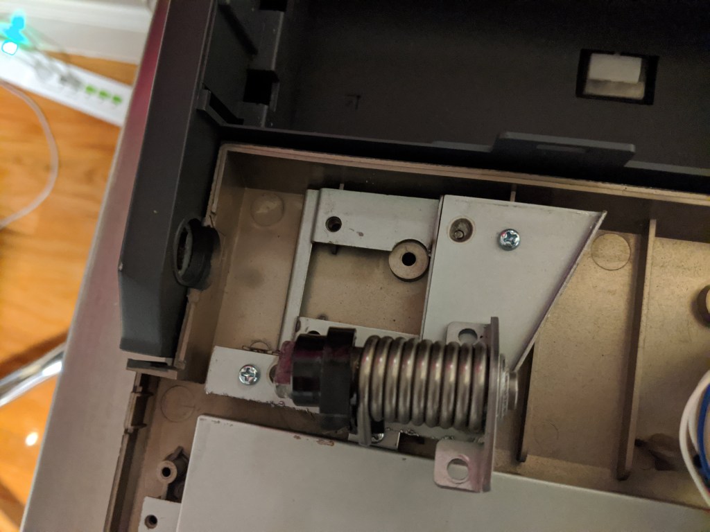
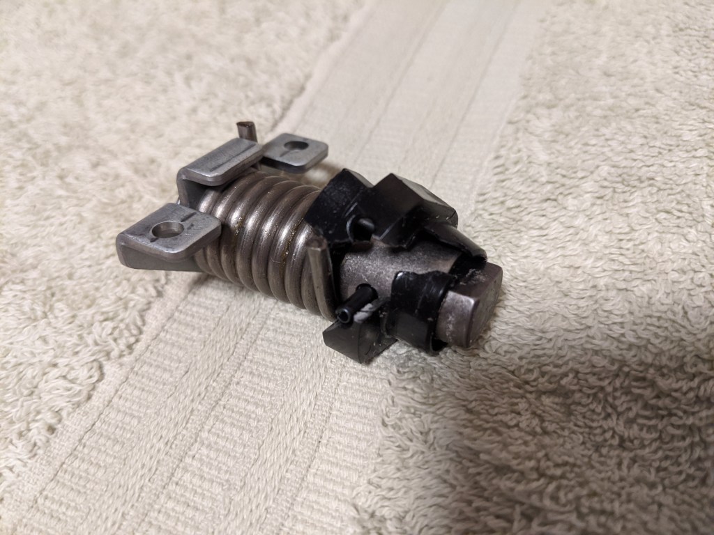
Remove the two screws holding it to the screen door, and you will be able to easily pull it out (WARNING: I have been told (Thank you DarkLord!) that in some cases, the spring snaps with no tension after unscrewing it. It was not my case, but be careful!). As you can see in the third picture above, mine has a broken plastic piece (it seems to be an stop for the spring), but before I took apart the piece I never noticed anything wrong moving the screen. I hope it behaves the same when I put it together…
You can now remove the screen door (last picture) and put it aside (notice that, in the picture I took, the power cable for the LCD screen is still connected and the tube holding the cables has not been removed; do as I say, not as I do).
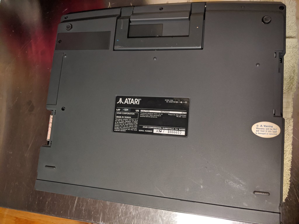
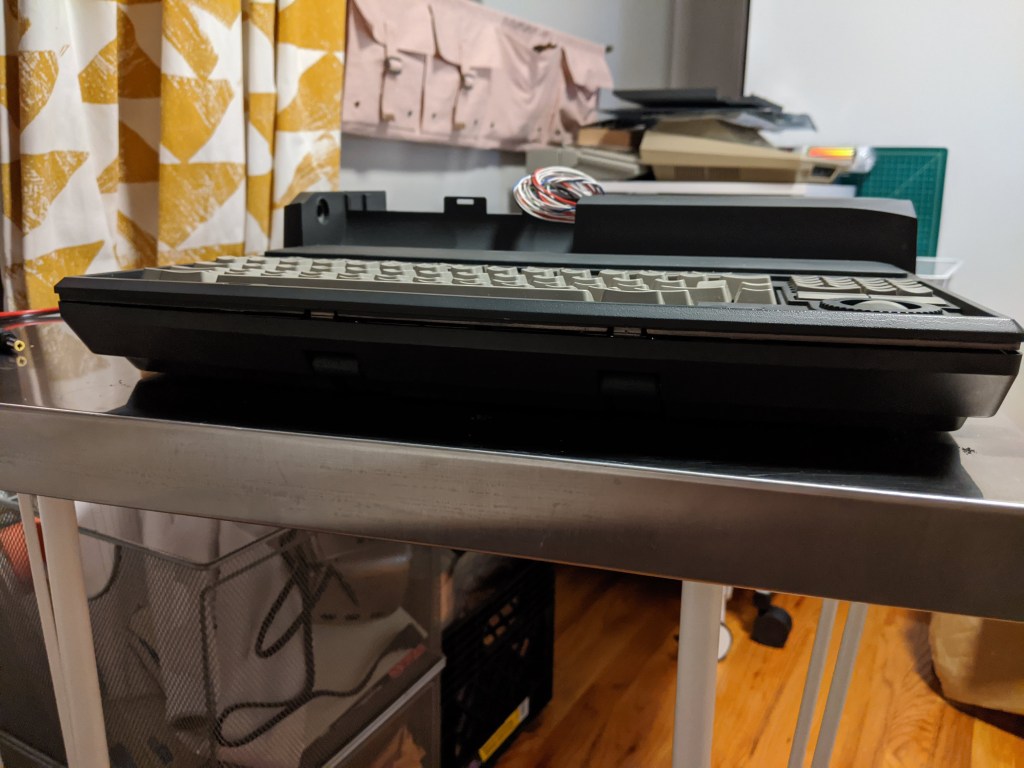
Now, turn the Stacy upside down; you need to remove 7 screws:
- 3 screws along the front edge (the one with the handle)
- 2 screws in the middle of the body (both are at about the same distance of the back edge); one of the screws may be under the Atari warranty sticker
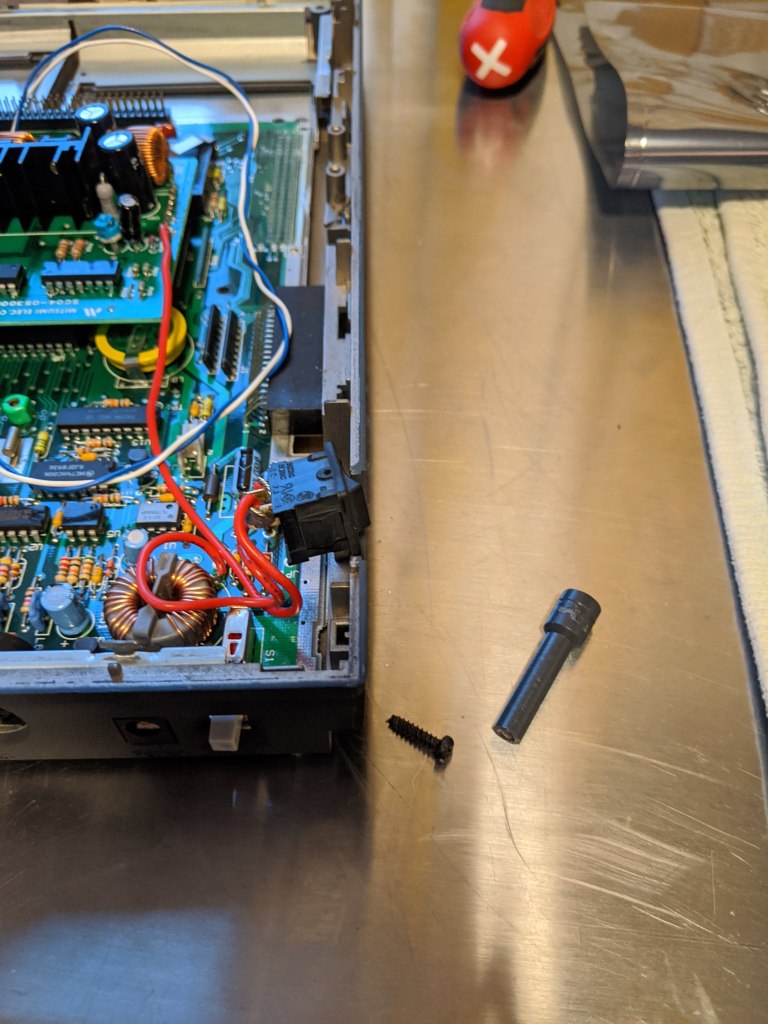
- 2 screws in the back of the Stacy
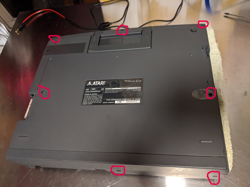
You don’t need to remove the screws of the two small doors (at least not yet).
To separate the top and bottom part of the main body’s case, you need to push the tabs located along the border:
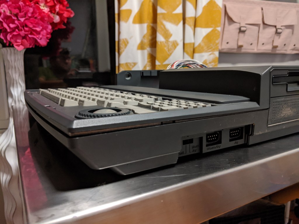
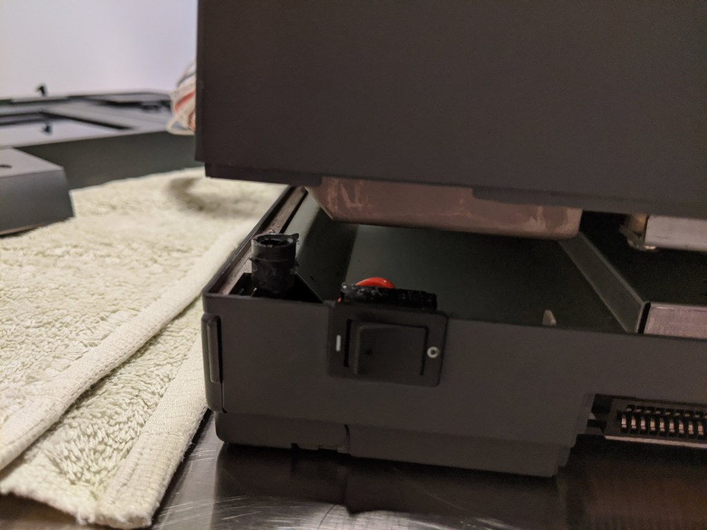
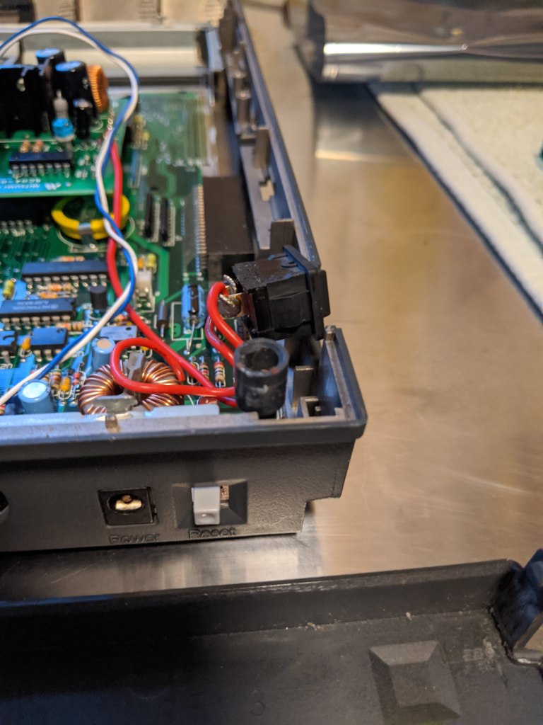
On the left and right sides, there is only one tab (on each side) located in the middle between the front edge and the taller part (see first and third pictures). On the front, there are two tabs located right above the hinges of the handle. On the back, in the left corner (near the on/off switch), you can pull the corner up gently, and it will come out of the plastic support (see first picture below). The tricky part comes now: the only thing holding the top plastic to the bottom is the faceplate of the disk drive. There is no clear way to describe how to remove it, other that have a lot of patience, and wiggle (gently) the top part; eventually they will separate!

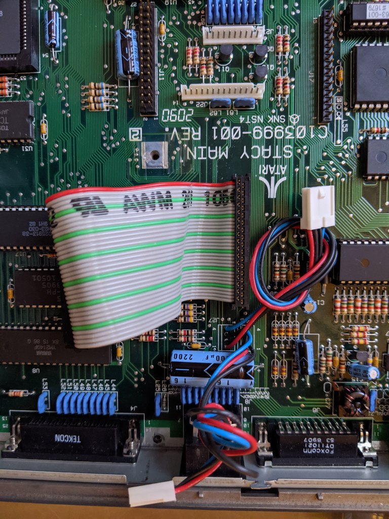
By the way, in the second picture above you can clearly see the goo, in between the two plastic pieces, that comes from that Conner hard disk.
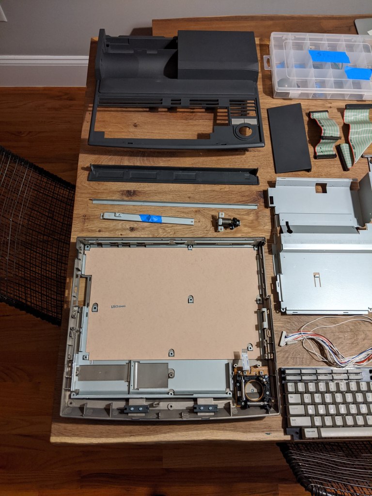
At this point both part can be separated (see fourth picture). Pass the cables through the hole of the top part, and you can put it apart.
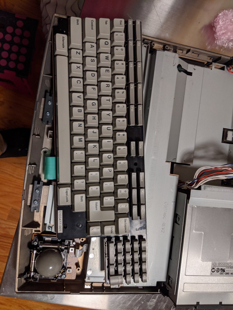
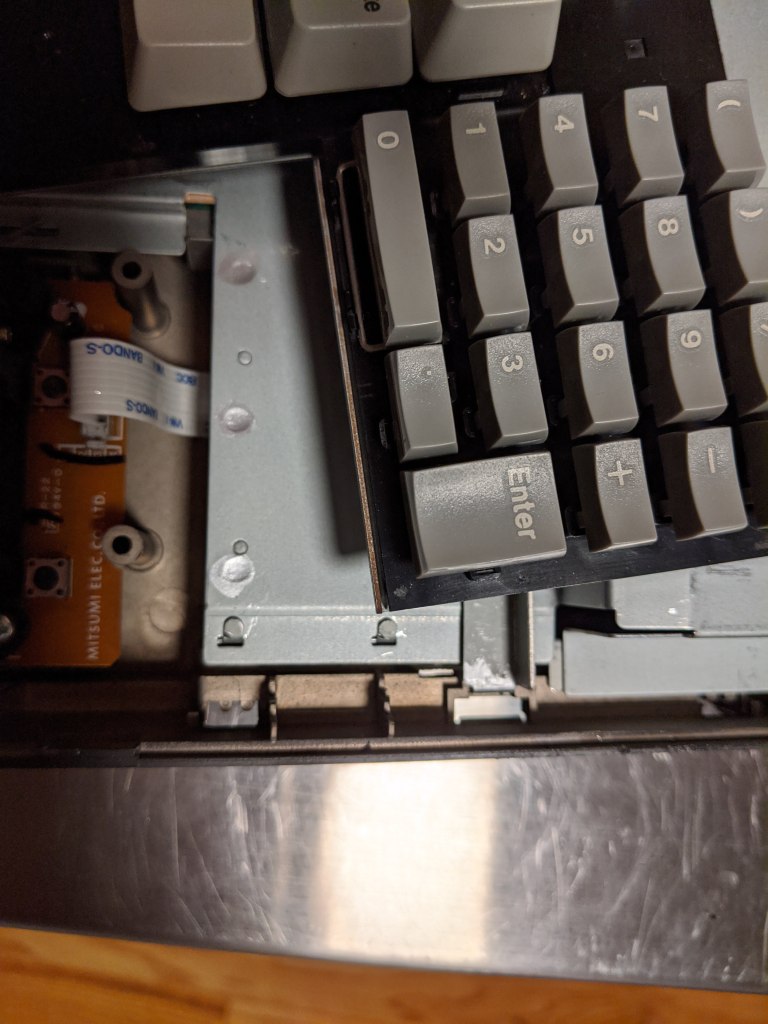
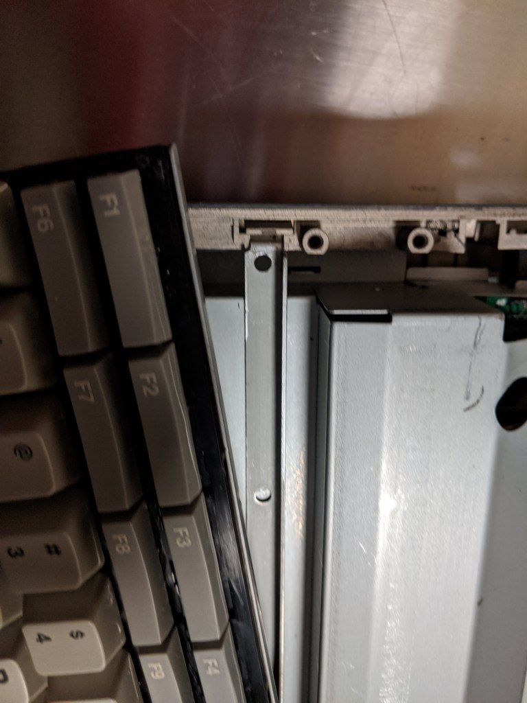

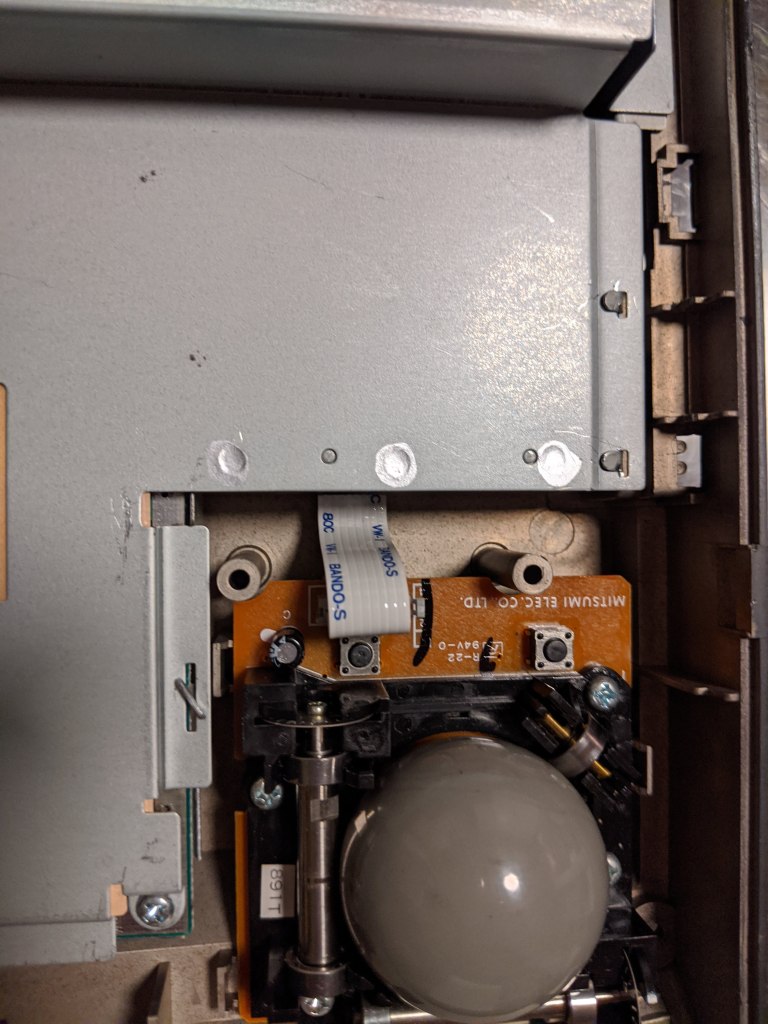
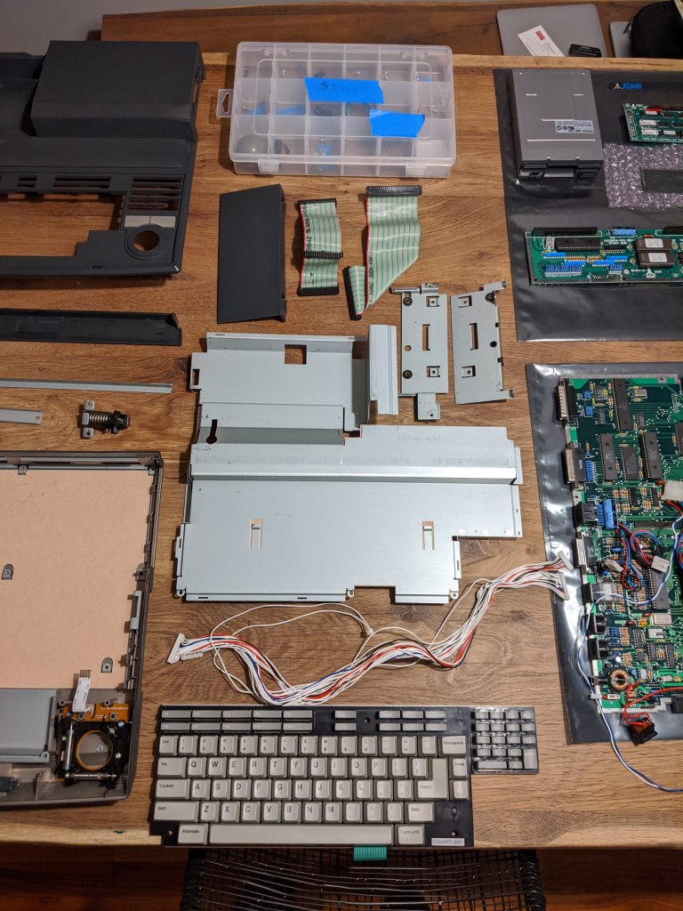
If you gently move (not remove!) the keyboard, you will see there is a metal bar, below the top edge of the keyboard, that cross the Stacy. You can pull the front part of the ZIF connector of the keyboard, remove the flex connector and remove the keyboard. Remove the metal bar. Also, remove the ball of the trackball, so it does not fall when you are moving the case around (me??? No, it did not happened to me…)
Metal tabs + screw 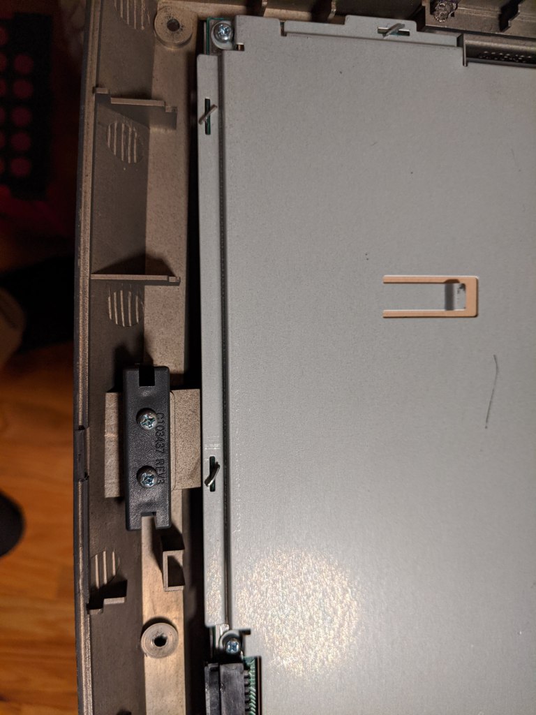
Metal tabs + screws 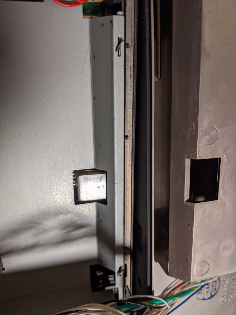
Metal tabs 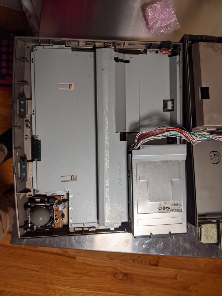
Break this ziptie! 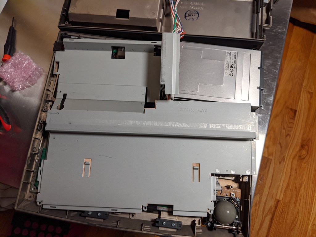
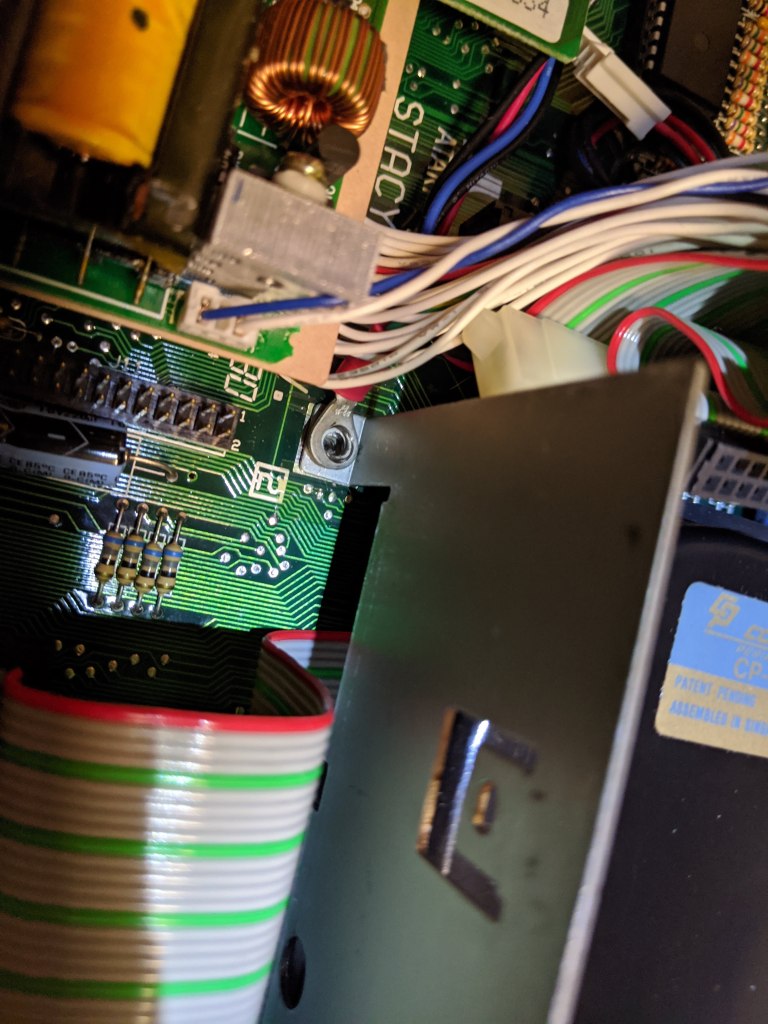
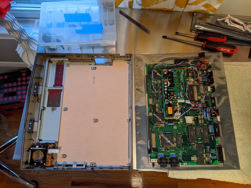
As all ST machines, to remove the metal shield you need to straighten the metal tabs coming from the bottom shield, along the border. Also, in the front border, remove 3 screws along the edge of the shield.
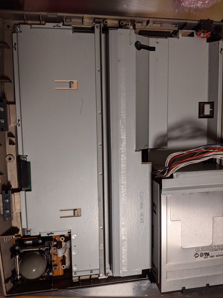
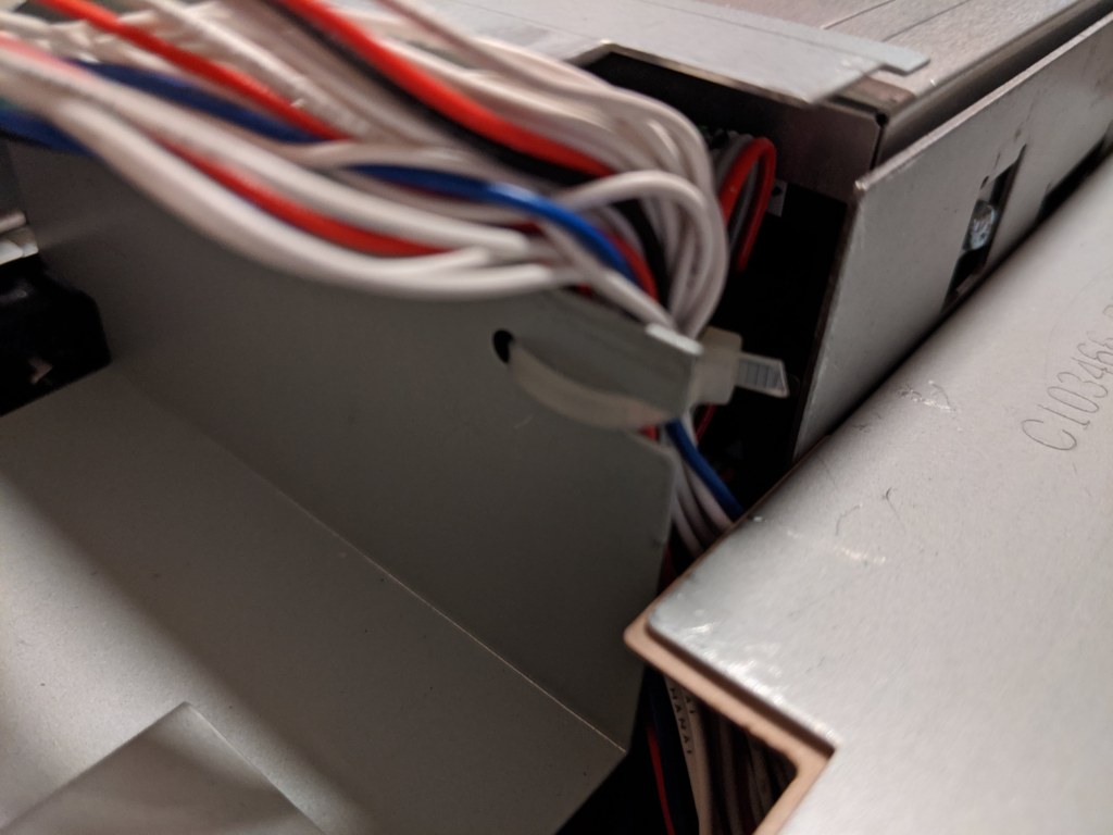
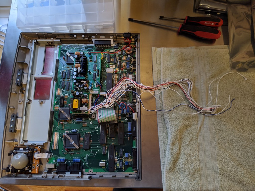
You will notice that all the cables come, from inside the shield, right behind the floppy drive. If you look at the shield and the cables, you will notice a zip tie; you will need to break it to free the cables and allow them to be moved out of the way. You can pull the top shield out (notice that, in my picture, the cables are still going through the hole of the top part of the case. This is only because I still had the power cable soldered to the LCD screen).
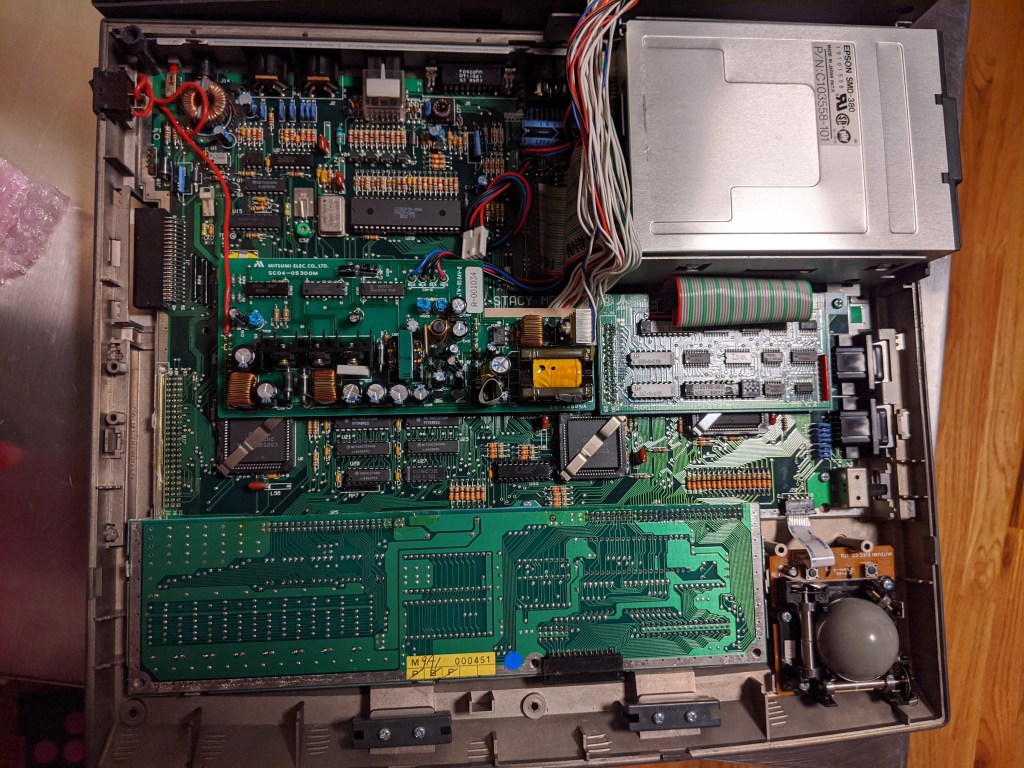
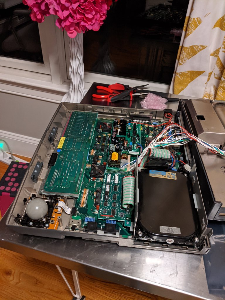
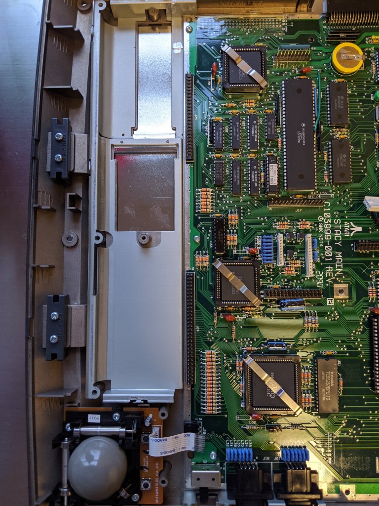
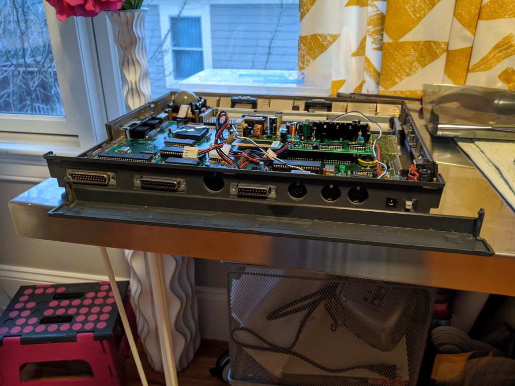
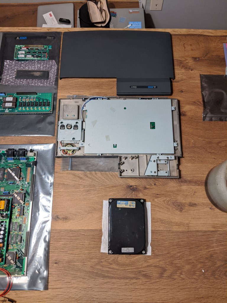
Now we are talking! Look at that beauty! It is incredible to think that, most probably, none of these components have seen the daylight (OK, I did this at night, but you get the idea) for about 25 years. Look at them for a minute or two, and let’s keep disassembling.
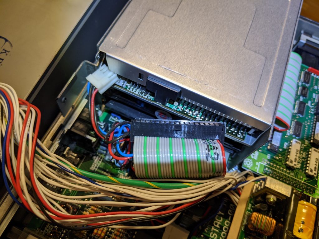
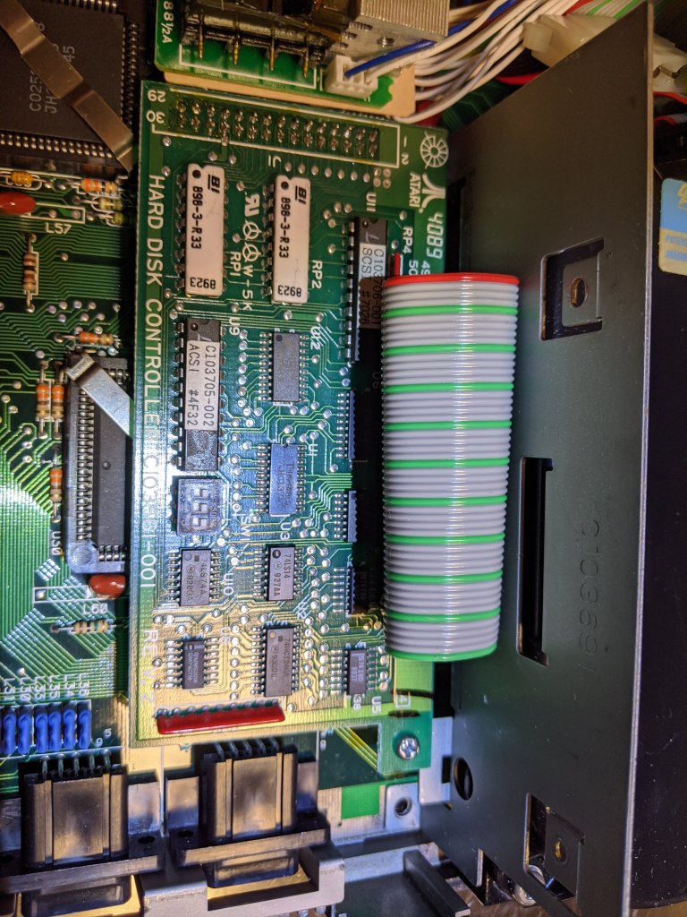
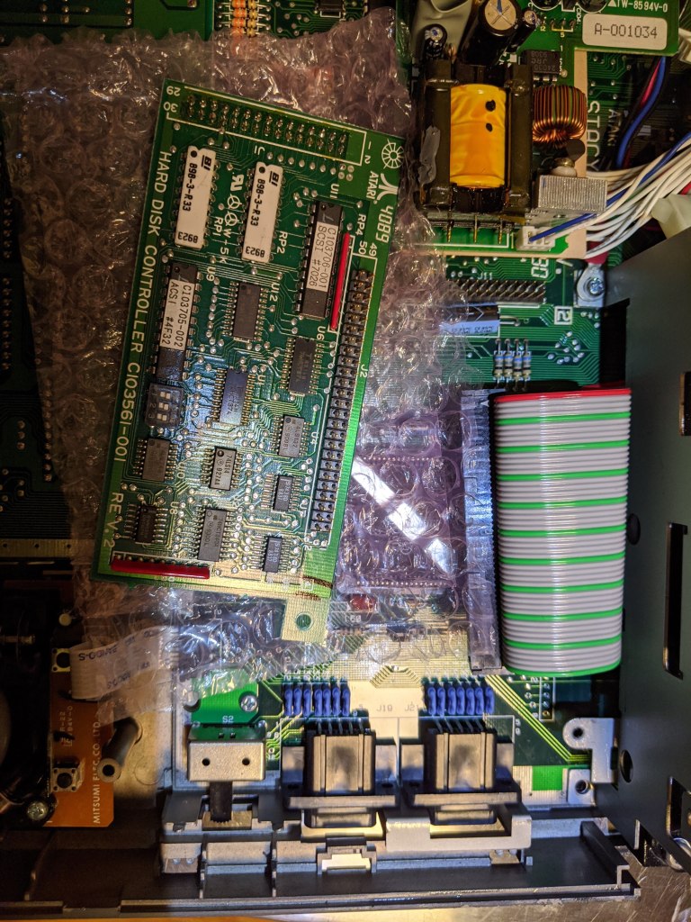
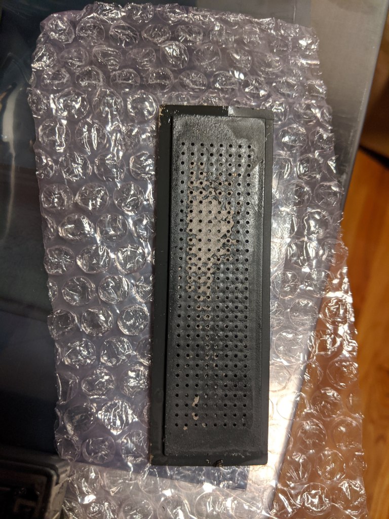
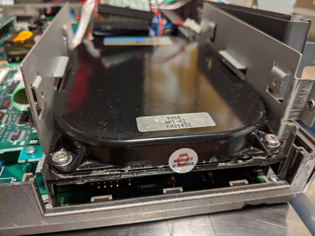
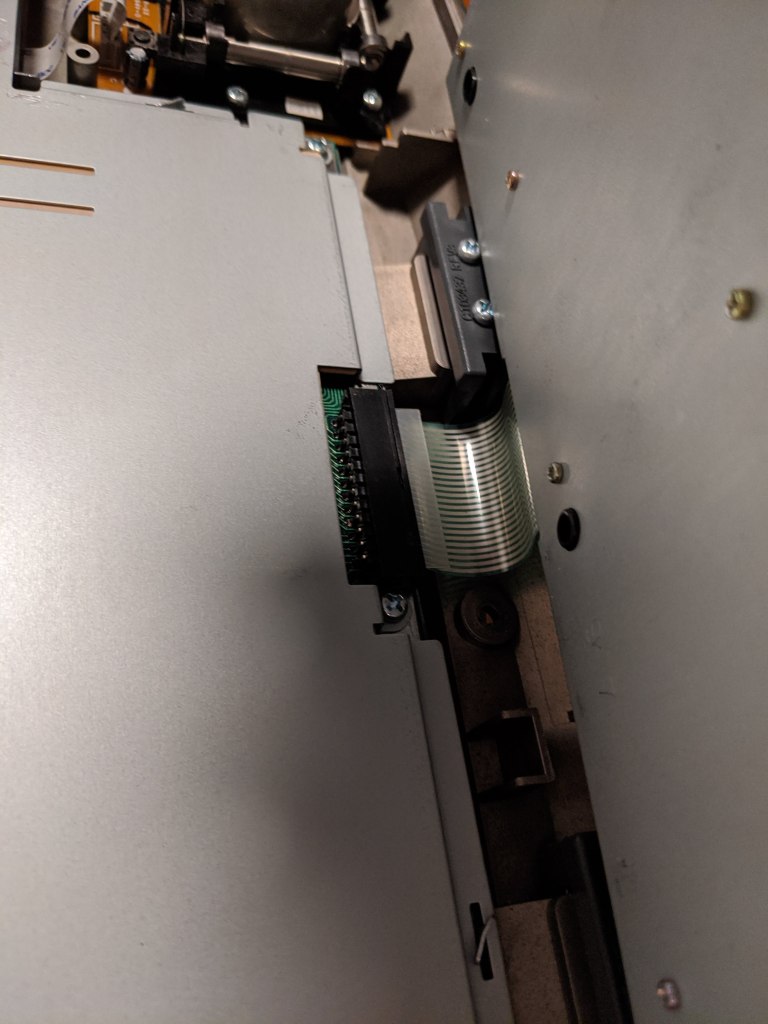
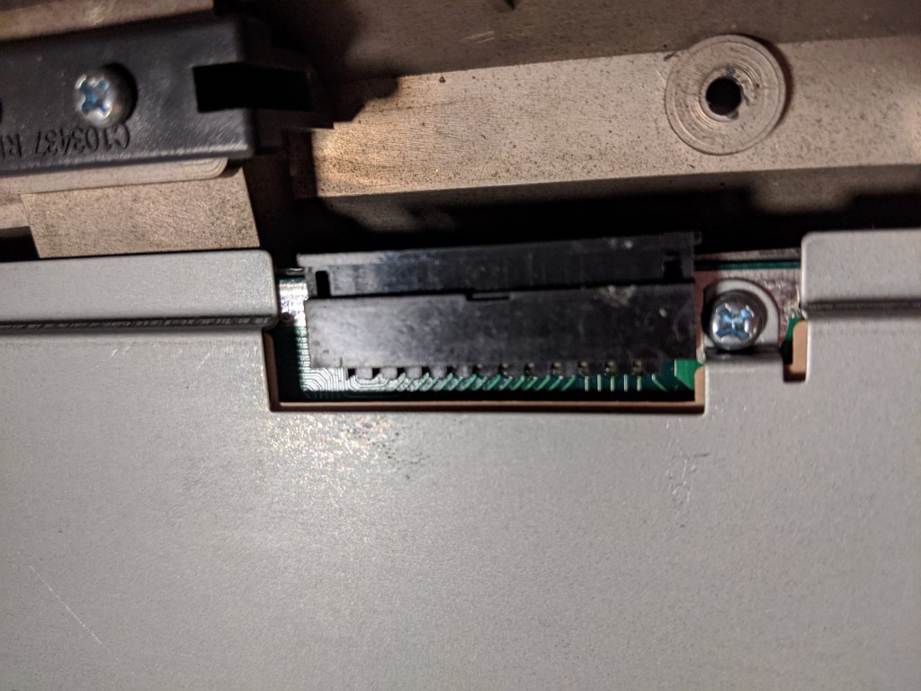
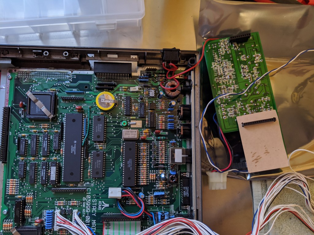
Once again, do as I say, not as I do: disconnect the power from floppy drive and the hard disk, and remove the data cable of the floppy drive. Next, gently, remove the ACSI-to-SCSI adapter/hard disk controller, remove the SCSI cable from it, and put it aside. You should be able to remove the plastic cover/front of the hard disk. In my case, a lot of goo (see also the front of the hard disk). Remove the 3 screws (2 back and 1 front right corners) holding the metal bracket of the floppy and hard disk, and you will be able to lift it. Notice that the ground cable for the LCD screen is screwed to the back left corner of that bracket.

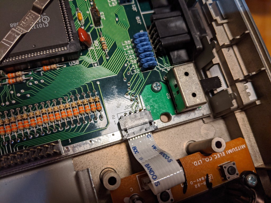
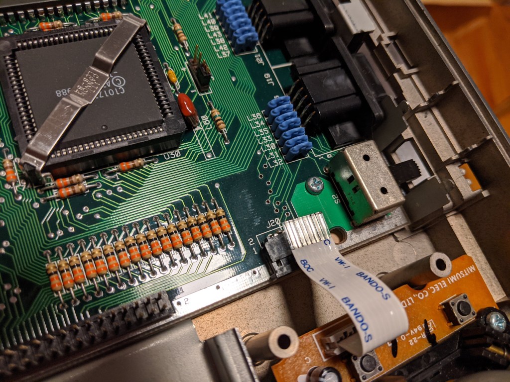
The front board, that hold the memory, TOS and keyboard controller chips, can be removed by pulling the card up, gently, from the two connectors that connect it to the main board. Also, it is a good time to remove the flex cable of the trackball from its ZIF connector (pull the front part of the connector, and you can slide the cable out).
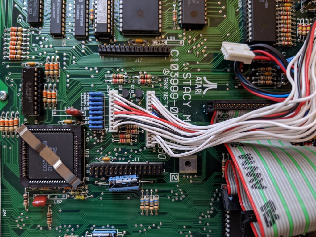

To remove the cables going to the LCD/speaker, you need to lift the power supply board; it is very easy to lift but, because it has the red cable (coming from the on/off switch) soldered, you cannot move it completely away. After removing that board, you will have access to the connectors of the cables, and you can pull them. Also, pull the floppy disk data cable. For safety, I connected the power supply board back.


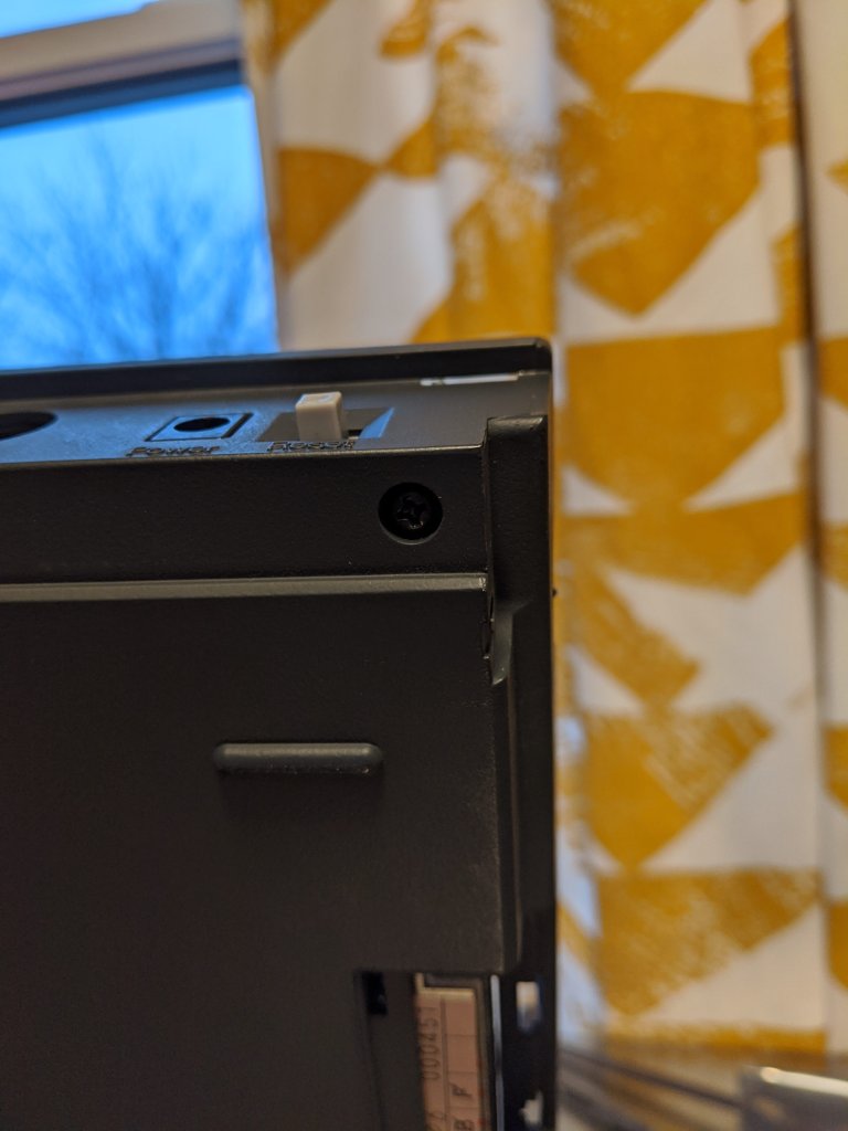

To actually remove the main board from the bottom case, you need remove the 3 screws in front of the board, and unscrew the connector holders of the serial, parallel and ACSI ports. Then, remove the back cover door, by gently pulling away one of the hinges. That will give you access to the screw hole of the plastic holder (the one holding that corner of the top case), that you also need to remove. Done! You can remove the main board out of the case. If you want to remove the bottom shield from the bottom case, you need to flip the bottom case and remove the two small doors near the handle (I did not do it).
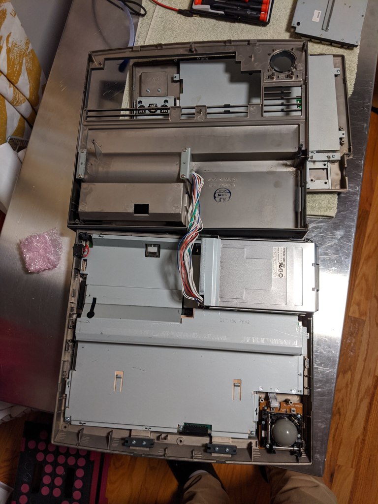
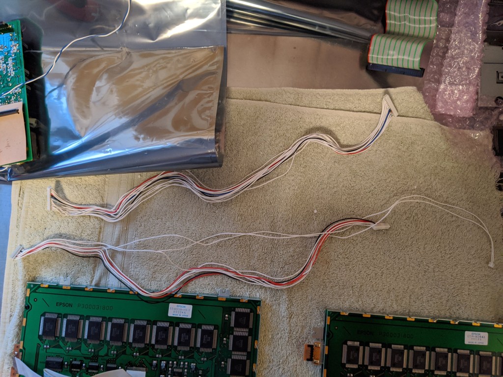
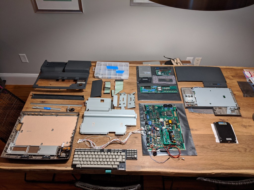
These are all the parts of the Stacy, disassembled:
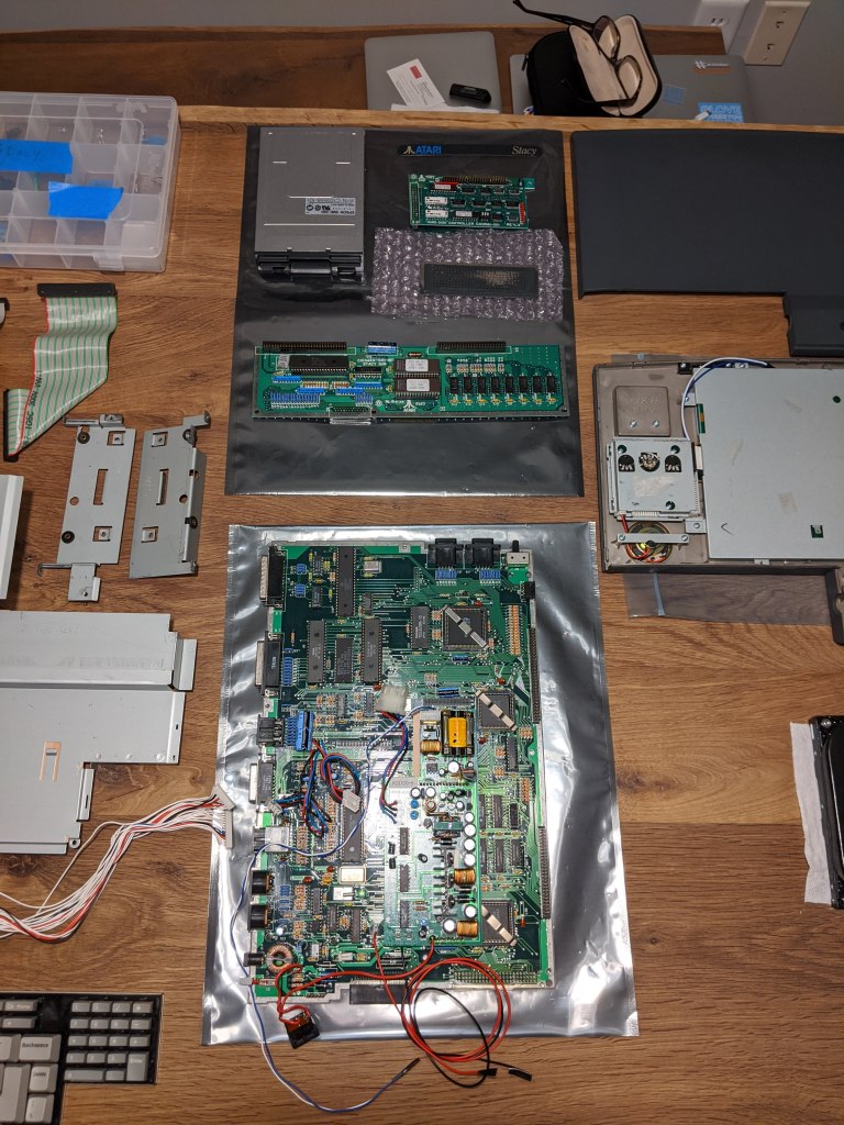
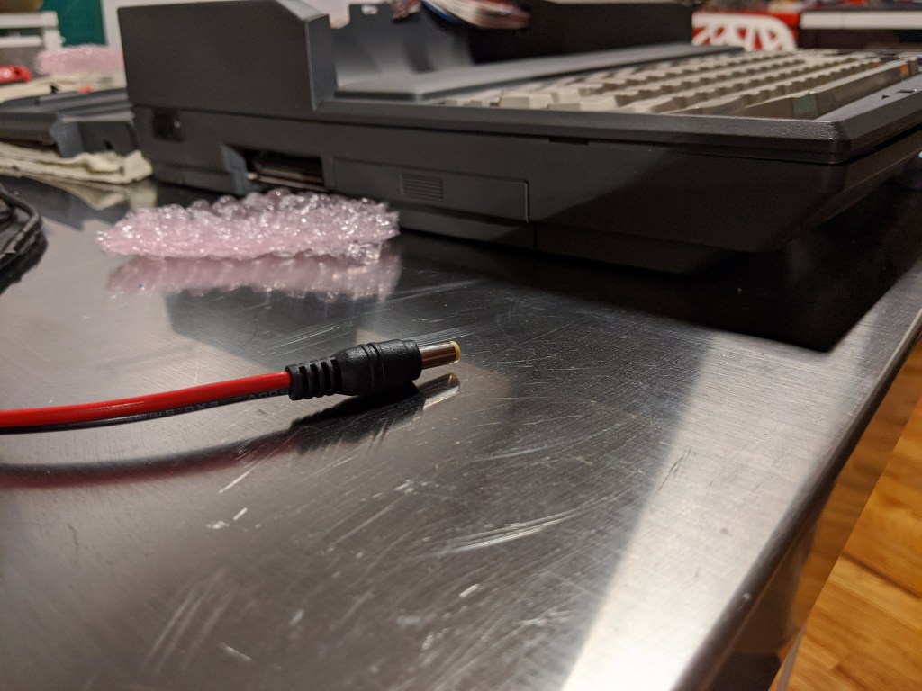
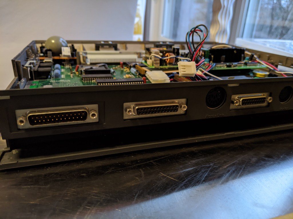
I was not sure if the Stacy would work without the LCD connected, so I give it a try, and it did!

In the next installment of this saga, I will start to fix/upgrade the things I mentioned in the first post.
