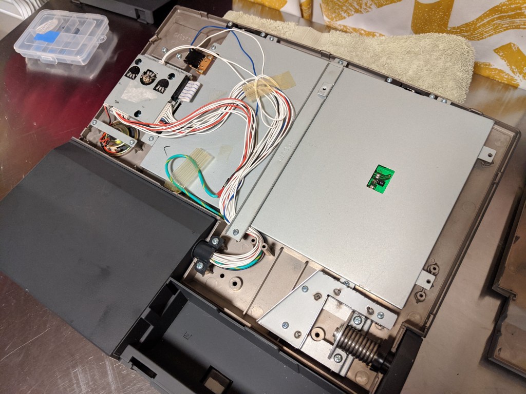
In part 1, I showed how to remove the back cover of the screen section. The next thing I did was to replace the LCD screen (the light in the original one was not working anymore). This is the current view:
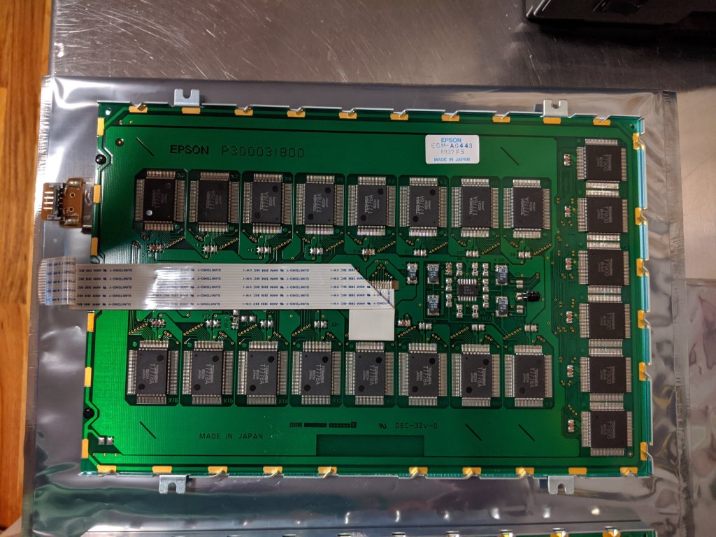
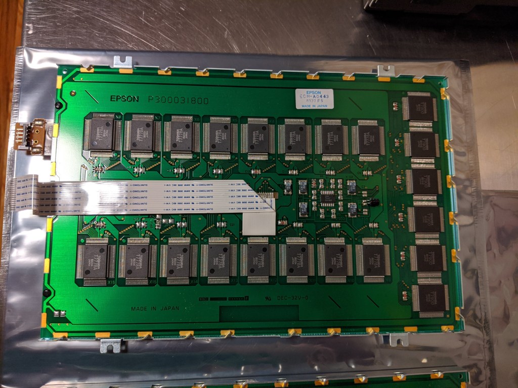
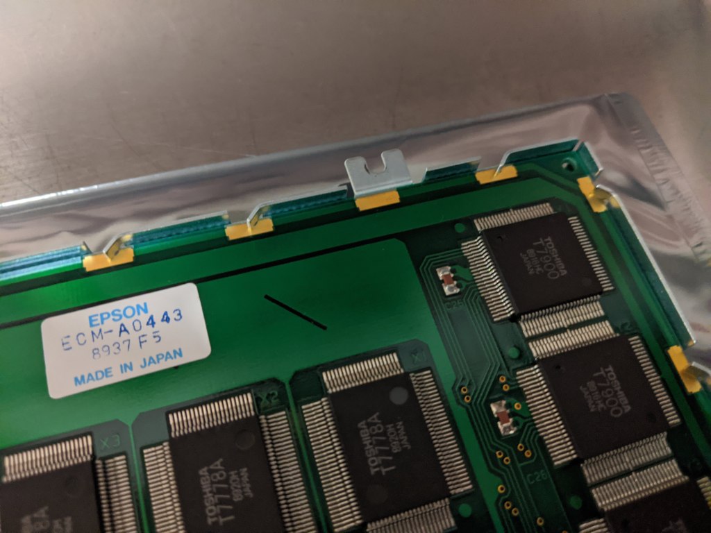
Before continuing, let’s talk about the LCD screen: the one used by Atari is an Epson P300031800, but the specific used by Stacy is not made anymore. There is an “industrial” one available on eBay, that has 3 differences:
- the frame has the tabs, for the screws, on a different position.
- the power pad doesn’t have a connector, and it is in another position.
- the flex strip is connected backwards (not a problem), and that makes the insulation/rigid “connector” being on the other side.
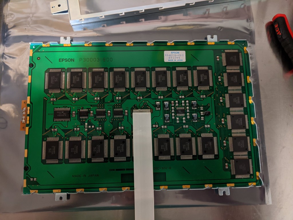
Original LCD 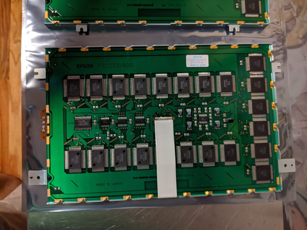
Replacement LCD
I will explain how to solve these problems later.
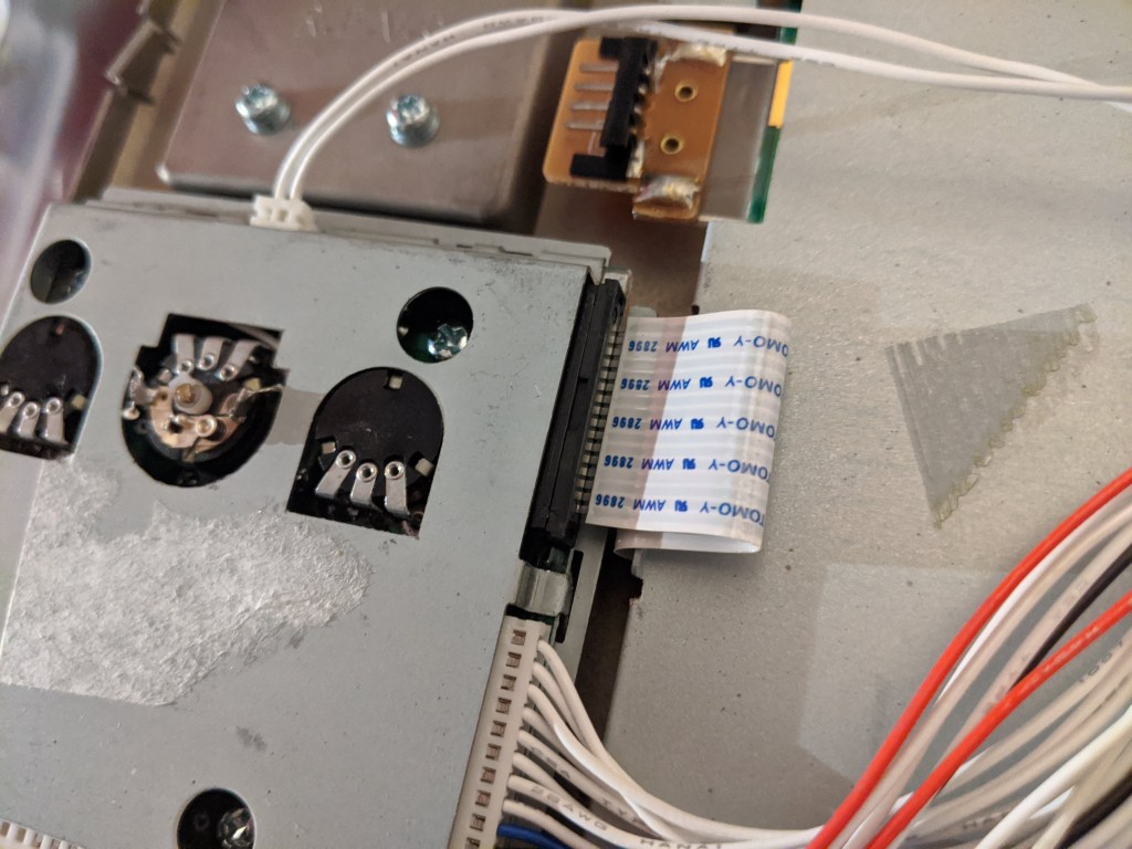
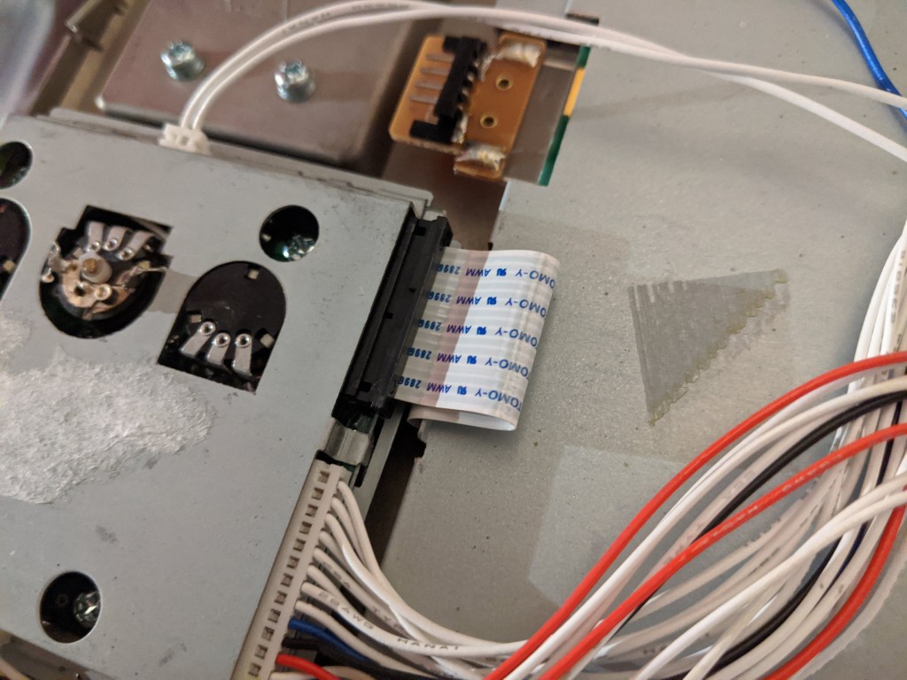
The first thing is to remove the metal bar across the LCD back; two screws and comes out. After that, disconnect 2 set of cables related to the screen:
- the black connector with blue and white cables; that’s the power. Just press the sides of the connector and pull (first picture below)
- the white flex strip that goes into the ZIF connector. You have to pull, gently, the border of the black connector towards the LCD (second and third pictures below).
Remove all the screws holding the metal backing of the LCD and the green ground cable; remove the metal back and you will be able to slide the screen out of the case:

To solve the problem of the positions of the tabs for the screws, you need to straighten the little tabs at the border of the frame of the original screen, then push the screen out of the frame:
Tabs holding the screen to the frame 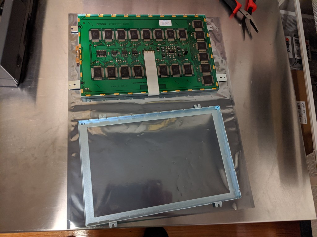
Bottom: empty original frame
Then do the same to the replacement screen but, after carefully lifting the replacement screen from the “new” frame, place the new LCD in the old frame; it fits perfectly. Twist the metal tabs of the frame back to their position (to hold the screen and circuitry) and you are done with that part.
Replacement LCD in original frame 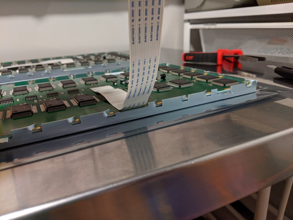
Flex strip glued to screen
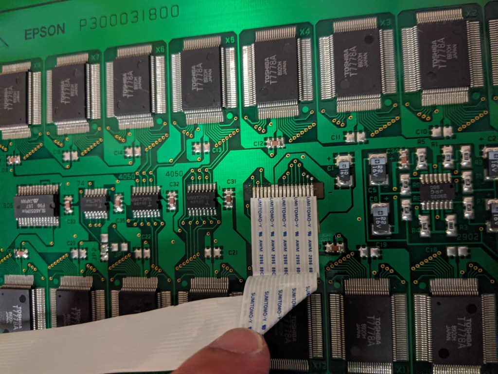
Now, the flex strip. First, carefully free the strip from the bottom part of the circuit board. Then, let’s focus on the part that connect to the Stacy:
Original LCD 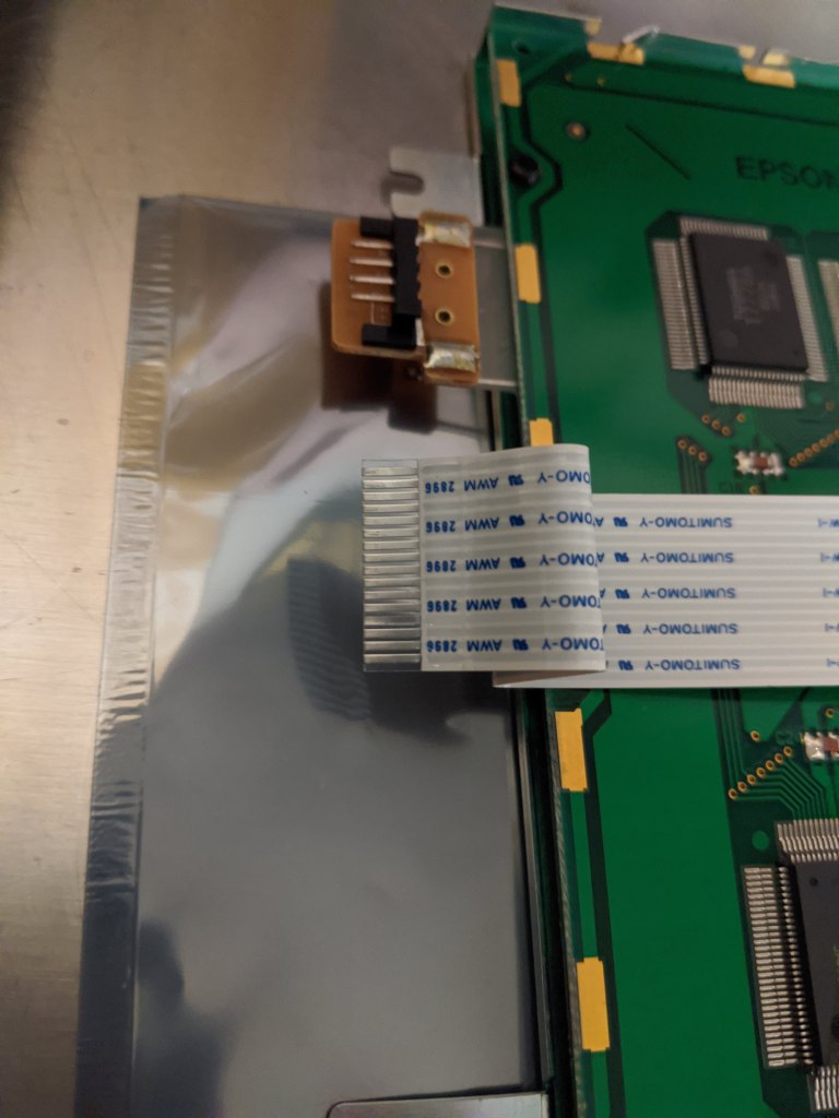
Original LCD 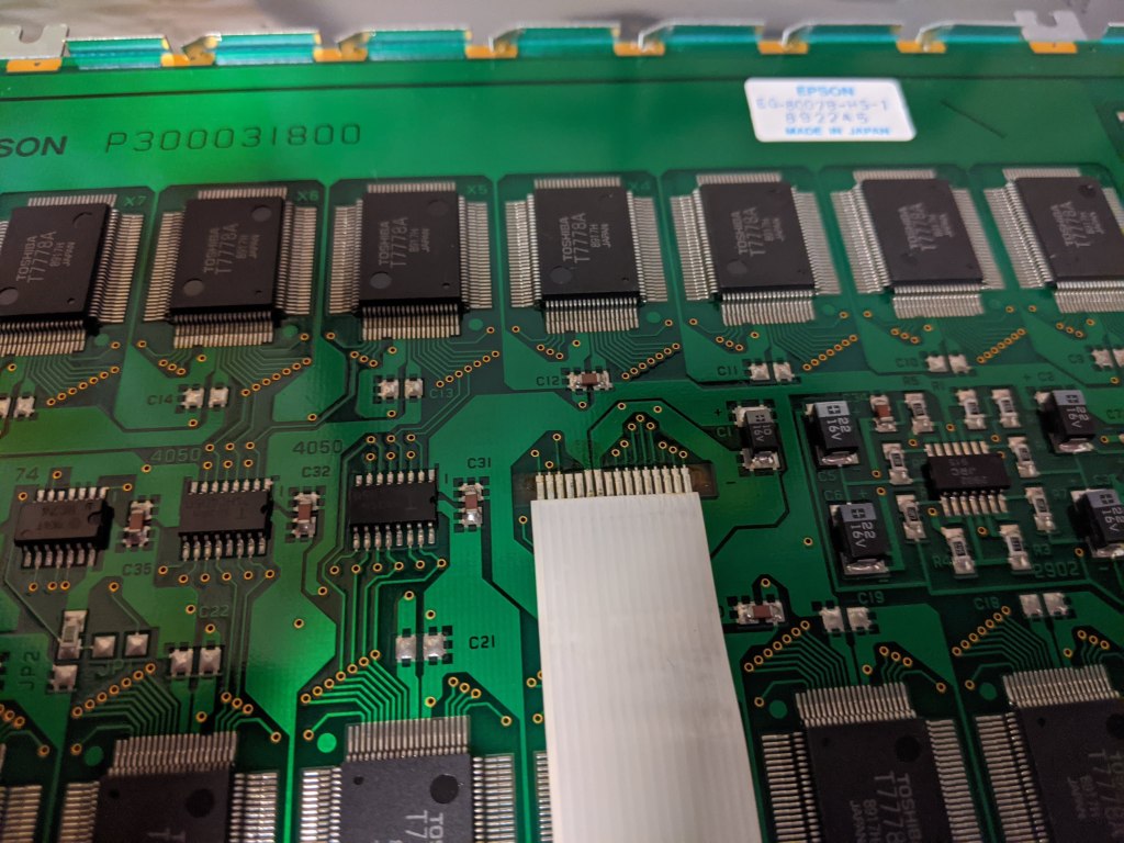
Replacement LCD 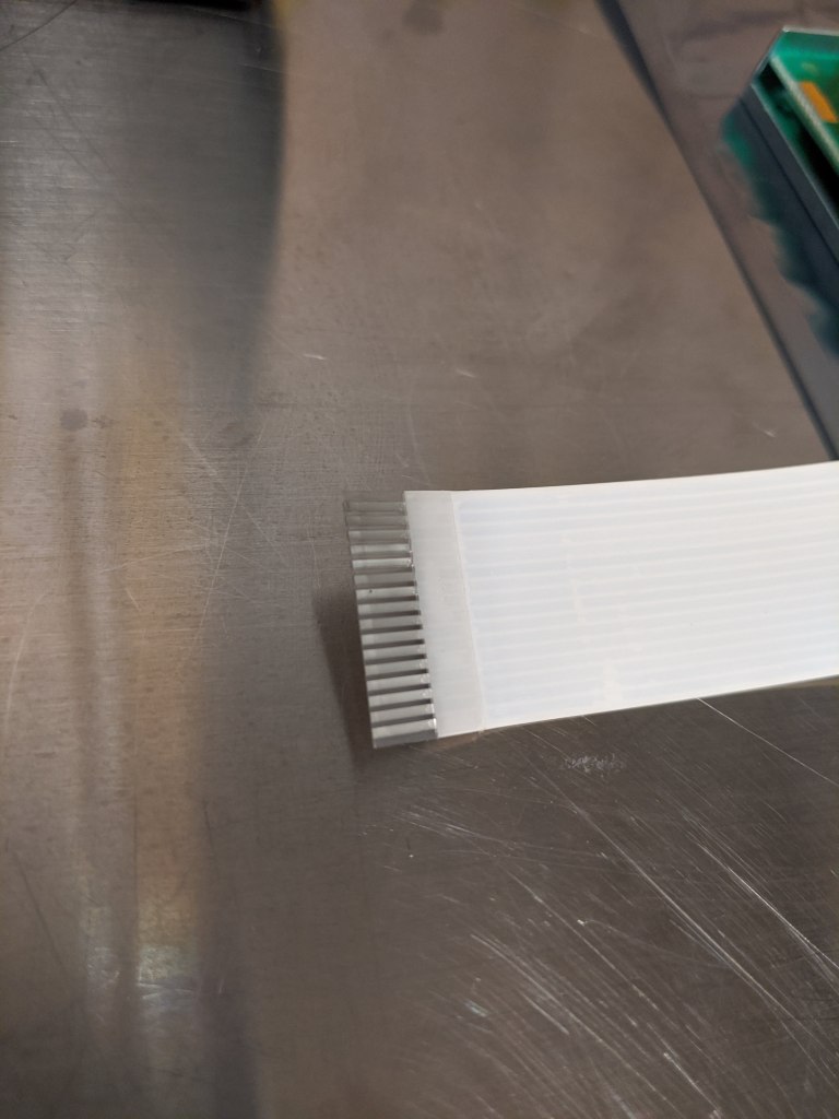
Replacement LCD
As you can see, the transparent plastic piece that makes the contact rigid is glued to the non-printed side of the flex strip, in both LCD screens. The problem is that the cable is installed backwards. To solve this, I carefully removed the plastic piece from the original screen (using the utility knife in between the piece and the flex strip), applied spray glue and glued it to the other side of the tip of the flex strip of the replacement screen. Then tried to remove the original plastic piece in the same way (didn’t work; it broke) and voila! I guess another option is to desolder the flex strip from the LCD, and then solder it backwards. I may try this in the original LCD, to see how easy it is and, maybe (spoiler alert!), use that approach in the future.
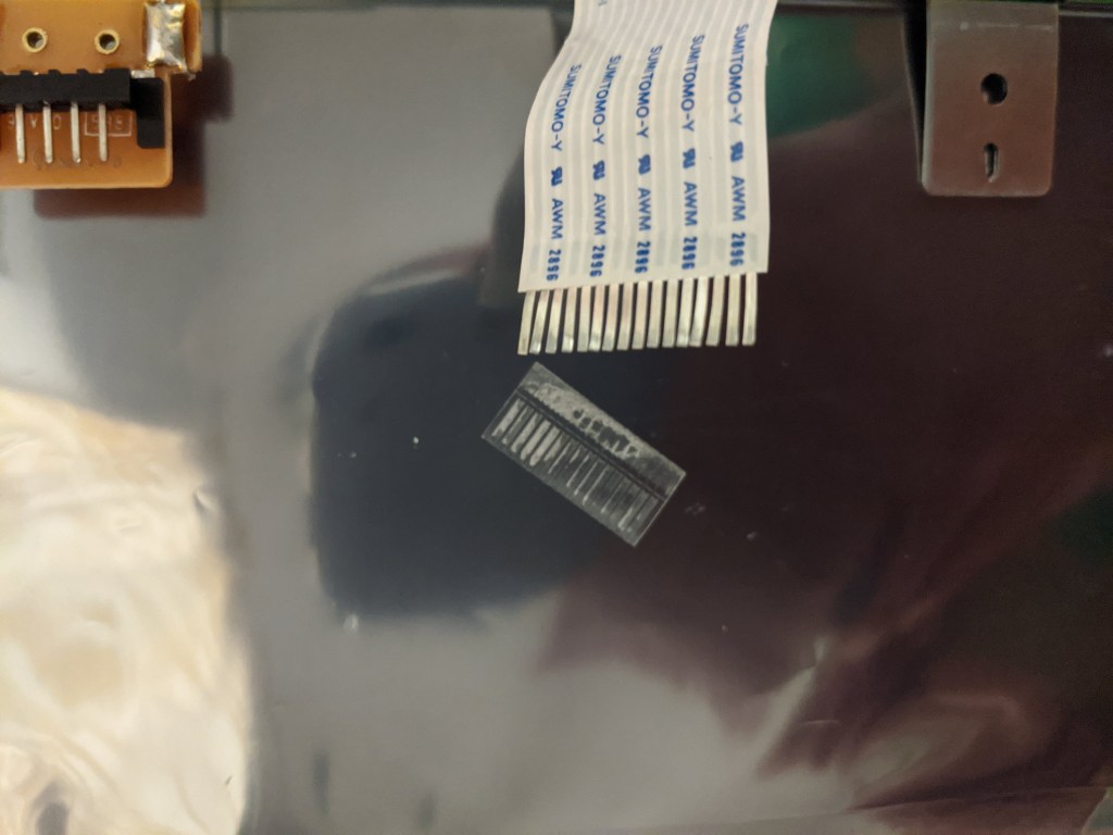
Original plastic piece removed 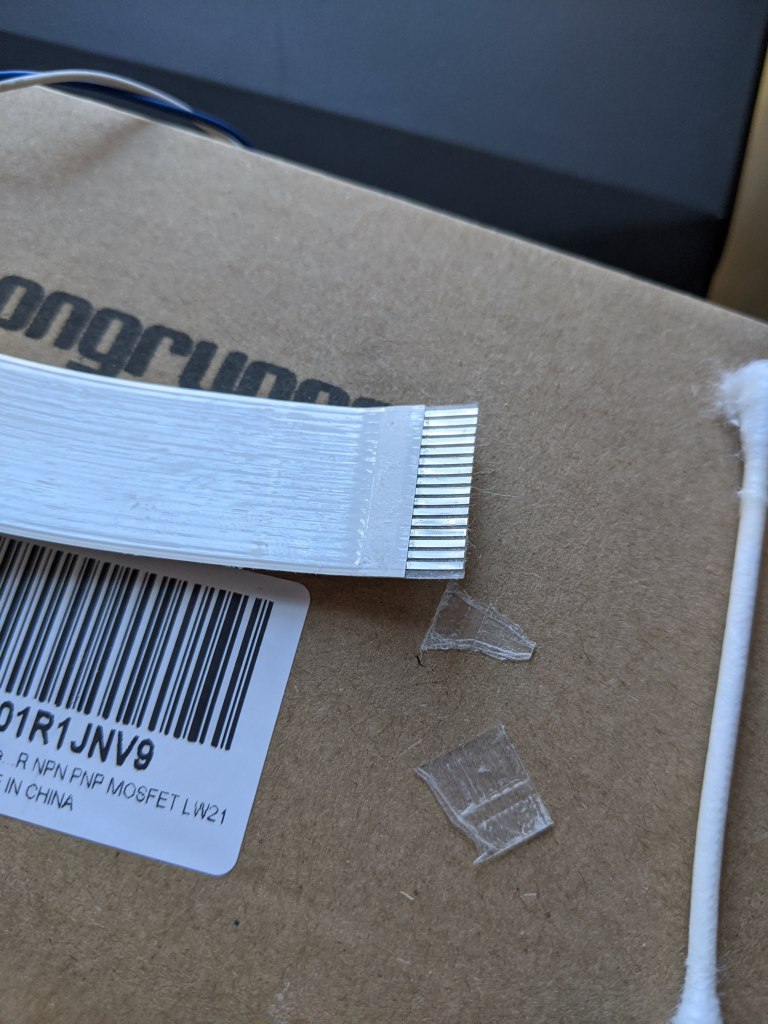
Original plastic piece glued and replacement removed
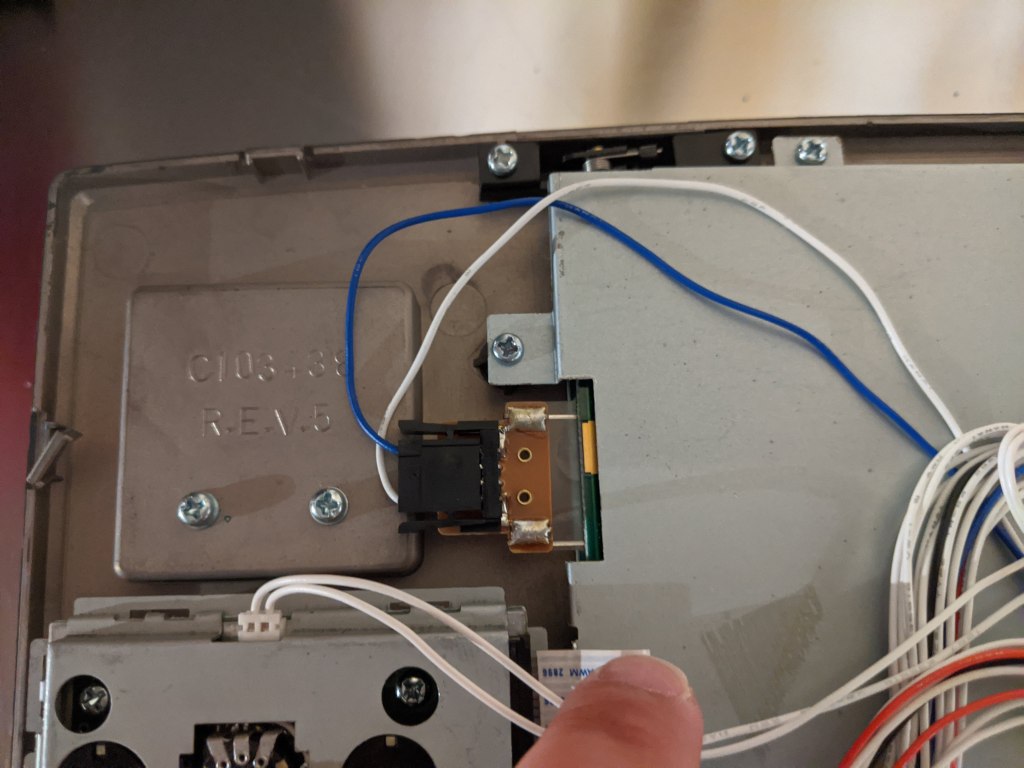
The final part is the power: in one of the instructions that I read on the Internet, the person solved the problem removing the black connector and soldering the cables directly into the pad of the new LCD. I followed this idea BUT then you get into a problem: to remove the whole door where the LCD screen is installed you need to un-solder the cables! So, I would suggest to install your own cables and small connector to the pad and to the white/blue cables, so you can disconnect them easily (maybe even use the same connector of the original LCD screen). Or, if you really want to solder the cables to the pad, doing it at the very end of the repair (after any work in the body).
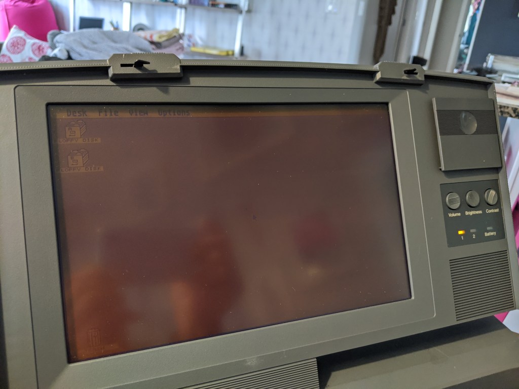
At this point I connected the flex strip back, installed the metal back of the LCD (but not the bar) and tested the screen. Success! … kind of:
Original LCD 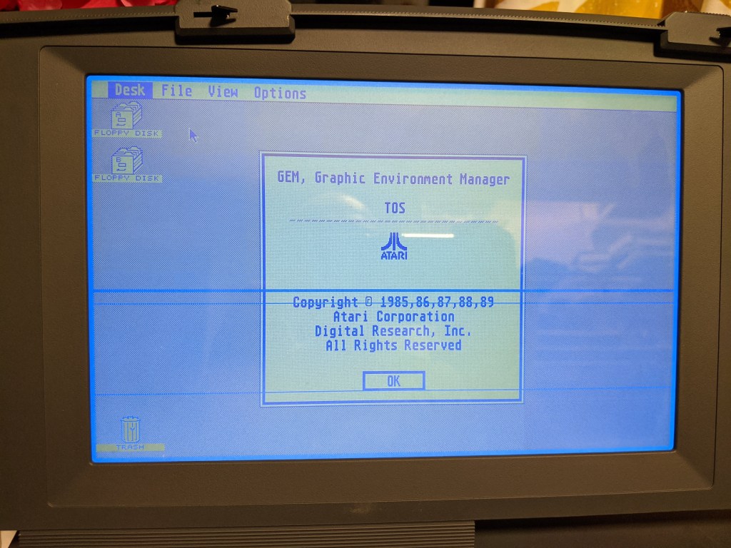
Replacement LCD
As you can see, there is backlight, so you can use the computer in any light conditions. But there are dead rows in the LCD! I don’t think I caused them, because I was very careful when transferring the screen from one frame to the other, but I don’t have a way to probe it. And because there are so many modifications to the LCD to make it work in the Stacy, there is no way the eBay seller will accept it back. So, I will need to order a new one and give it another try. This time, though, I will install wires and a connector to the power pad of the LCD, so I can disconnect the cables.
OK! Next post, hopefully, it will be my adventures on how I opened the body of the Stacy.
